Wednesday, August 12, 2020

PPG Beginner mistakes

Keith Pickersgill


The biggest mistakes that newbies make when converting from PG to PPG;

1) leaning forward on the take-off run. No need to lean backwards, but run as upright as possible. 

2) running on quarter-brakes like a slope-launch. When launching off level ground, build up your speed on zero brakes. When you reach takeoff speed, just a light touch on the brakes to lift-off. Much less than slope launching. Once airborne and climbing, slowly ease off the brakes. 

3) flying on brakes is a big no-no under power. Level flight and climbing must be done on zero brakes. Only slow the wing down when flaring for landing. 

4) turning: don’t try to flat-turn like thermalling. You want the wing to bank over, then the motor pushes you around the wind, a bit like a slingshot.

5) They tend to sit way too soon - on a slope, and without a propeller to smack the ground, that is not usually much of a problem, but its more critical when PPG off level ground - wait for a positive climb rate before lifting your feet -  you might touch down once or twice just after you think you are flying, so keep your legs down, ready to run a bit more until you are definitely climbing.

6) Newbies tend to be afraid to use all the power for launching - once you decide to go onto power (more about that later), you need one-hundred and plenty percent power, everything the motor has got, unless you are an experienced pilot and you have surplus power, then you can do a low-power launch.

The correct power input to launch off level ground, whether its a forward or a reverse launch (excluding short-field technique which I'll cover later), is to stay completely off the power until you are running with the wing fully overhead, not hanging back, and not off to one side, and you still have enough runway in front of you... up to this point, its not yet a launch, its still just a pullup... you need to make that tactical decision, when to go onto power, with everything under control and enough runway ahead, then you go to full power!!!!

Things tend to go wrong in the time from when you start applying power, until you actually lift-off.  You want to reduce that to the shortest possible period of time and the fewest possible steps, to reduce the risk of damaging anything. 

So once you decide you have everything under control, go to full power and sprint the next few steps, on zero brake, then once the motor starts to peak, apply just a tiny touch of brake to lift off.

Short-field launch is different. If there is enough wind, then obviously you need very little runway - you can pullup in reverse mode, walk downwind to where the wing's leading was laying on the ground, turn around, apply power but resist the thrust for as long as you can, then burst into a sprint. In only 10kph, this can reduce your takeoff run to under 5 steps.

Its the light or zero wind launches off a short field that needs a special technique...

Firstly, 90% off pulling off a successful forward launch in zero wind, is the wing preparation ands layout. Off level ground, this is far more critical than off a slope.

Get that perfect leading-edge curve. Fold the closed cells concertina fashion on top of the adjacent open-cells (preventing one wingtip coming up before the other). Stretch out your lines, make sure they are free of snags and twigs. Then stand halfway to the side between the center and the one wingtip, take only the main brakeline in your hand, and pull that towards the risers lying in the center, fully stretched, getting the wingtip section to curve a bit more. Repeat the other side. 

Then, strake all the line, so that all the slack on the non-A lines lie near the risers, and not near the wing. You want every line coming off the wing to run dead straight towards the risers, with any slack lying by your feet. 

Then hook in, make sure you are absolutely centered to the wing, shoulders square to the wing, look at your Left wingtip (if you fly left-hand throttle and turn out to your right on a reverse pullup), without twisting your hips or shoulders (biggest mistake!). All of that applies to all forward launches off level ground.

Now for the short-field launch, lean slightly forward, bring the motor up to 30% to 40% power to warm it up (leaning forward so that you do not blow the carefully prepared wing into disarray), then while holding that power level, very very slowly come upright, watching the wing over your shoulder, until you see the leading edge feeling the wind. If your A-lines are taught as they should be, you an move forward mm by mm until you see the prop-blast entering the leading edge, inflating the wing while it is lying on the ground. Hold this for a few moments, until you see the bottom skin lift up off the ground, indicating the wing is pre-inflated on the ground.

Now, you dump the power down to idle but immediately start a hard takeoff run.

Don't wait for the revs to die down.

If you do this right, the wing will absolutely leap up off the ground and be fully overhead in 2 steps or less! Be ready to tap the brakes if it wans to overshoot, which is likely on some wings, but then ease off the brakes once the wing is stabilised. As soon as the wing is fully overhead, go to full power and start sprinting.

If done correctly, you are off the power (from pre-inflating the wing on the ground) and back onto full power in about 3 seconds, and will launch in less than 8 steps on most wings.

Thursday, July 4, 2013

Measure the squish & set the timing on the PA125


How to check the ignition depth is correct without having to disassemble the motor.

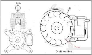
Without dismantling the engine, remove the spark plug and insert a length of solder to measure the "squish", or the distance between the piston at TDC position (TDC) and the cylinder head. This distance, called squish, must be between 1.3 mm. and 1.5 mm.

By inserting the solder and literally crush it with the cylinder head you can measure the thickness of the resulting solder crushed between the piston and the cylinder head. Remember that you must insert the solder until it reaches the cylinder wall and parallel to the pin and centered on the circle (see photos below)

Once satisfied that the squish is correct. See that the position of the flywheel is correct according to the scheme and provided with the piston at the point of maximum compression or PMS Measurement

Place the solder in the middle of the hole parallel to the piston bolt.

Measurement of solder after having crushed the piston against the cylinder head.

The distance between piston and cylinder head at maximum compression (piston at TDC) must be between 1.3 and 1.5 mm.


Gauge that is use to find the P.M.S. of the piston. It screws in place of the plug. It is the engine to manually rotate the piston up or down and so find out the PMS Tamper.


Once assured that the piston is at P.M.S. we see that the mark of the magnet and stator is 1.5 mm away from the coil.

Tuesday, January 15, 2013

Radio Squelch setting tutorial

Keith Pickersgill


I am constantly surprised that so many pilots do not understand what the Squelch setting on their two-way radio does or how to set it properly, so here goes a mini tutorial:

The purpose of the Squelch is to mute the speaker/headphones when there is no signal being received, to save you from listening to static noise and to save the radio batteries.

When the Squelch level is set correctly, the receiver will be silent until the radio receives a signal from another radio, then the speaker un-mutes in order for you to hear the call.

The higher your Squelch setting, the stronger the incoming signal must be in order for you to receive it.

If you set your Squelch to high, you could mute some weaker radio calls and will not hear them.

If you set your Squelch level too low, the constant static noise in  your ears will affect your ability to concentrate and causes stupid mistakes to be made in flight.

The appropriate Squelch level depends on the ambient RF (Radio Frequency) noise conditions, which varies from place to place and from time to time.

It should be set at the start of every flight, or at least checked that it is not too high.

How to set your Squelch:

First, set the radio to the frequency you will be using for takeoff.

1) Turn the Squelch down (anti-clockwise on the dial, or the down-arrow, depending on brand/model of radio), until you hear the static noise.

At this stage, you can use this noise to adjust your volume control, saving you from asking someone to give you a radio check for the purpose of setting your volume.

2) Now gradually turn the Squelch up until it just mutes the speaker and the radio goes silent (if no-one else is transmitting on this frequency).

3) Now start your engine and during the warm-up, listen to see if the increased RF noise from your ignition system opens the Squelch (the speakers emit Static Noise again). If this happens, increase the Squelch just enough to mute the speakers again.

4) You might find that when you switch on your GPS or camera or other electronic device, your Squelch opens again, in which case you increase the setting again just enough to kill the static.

Once you have an idea of how much you need to increase the Squelch to compensate for engine, camera, GPS, etc, then in future, Do step (1) above, then increase it by that amount (rather too little than too much).

In flight, once everything is on, you can check the squelch by adjusting it downwards and the Squelch should open immediately, indicating that you had the correct level.

If you set the Squelch too high, which is the dead lazy thing to do, you might miss some critical radio calls which impacts on your own safety and that of other aircraft.

Note: Your squelch setting has absolutely no affect on your transmitting, your microphone or how others hear you over their radio.

It affects only the receiving audio.

The next time someone tells me their radio is causing lots of interference in the air and it turns out to be merely their squelch setting was too low and they were listening to static noise the entire flight, expect a kick up the backside!

Listening to static noise in flight affects your ability to concentrate, causes headaches, and causes your hearing to eventually shut down,  so you do not hear when others call you.

Its not a difficult thing to get right.  Read this tutorial again if you are not sure.
If you still do not understand, now is the time to ask...

Prop repair

Keith Pickersgill

Q-Bond remains the best option for Carbon Fibre props. It is the same density as Carbon, hence no need to re-balance the prop if you do a careful repair. Easily worked with a file, sandpaper or my personal favourite, a Dremmel. In some cases, gentle application of an angle-grinder or bench-grinder can be used for the first prep before changing to something less drastic. Finish off with 1200 grit water-paper and polish on a piece of leather, delivering a perfect finish.

For wooden props, Epoxy is best. Either the two-part quick-set Clear epoxy (Prattleys, et-el), or the UV activated version such as Anthony's Dura Rez (and many similar brands).

Unfortunately Epoxy is a VERY different density to Carbon, so most epoxy repairs would require extensive re-balancing on Carbon props, though its good for filling very small cavities in Carbon.

Some tips: With the UV activated resin, work indoors (or in the shade under a tree if outdoors), then when you have the resin just where you want it, step out into the sunlight to cure.  You could partially cure in sunlight for say 30 seconds, then step back into the shade to check and adjust, and repeat as often as required if you want a perfect job.

For Q-Bond, the liquid part is ordinary super-glue. Even the cheapest superglue from Chinatown outlets works just as well. For tricky jobs, get the slow-set Gel-type superglue, which allows you to form and re-form the carbon black powder as it cures gradually.
You will always run out of the superglue before running out of the Q-Bond Carbon Black, so buy a few very small tubes (3g) of superglue to add to your toolkit, at about R5.00 each from Chinatown or similar outlets. Once opened, you usually can discard a bottle of superglue unless you keep it in a fridge or keep it perfectly upright in storage.

To fill a big hole in a hollow carbon prop, take the thinnest tissue paper you can find (one layer of 2-ply works well), stuff it into the hole and tease it to form the shape you want, then very gently wet the tissue with superglue. Wait for it to dry and become rigid, then re-wet small parts at a time and apply the Q-Bond Carbon Black in very thin layers.

Build the Q-bond to slightly proud, then grind/file/sand down to shape then polish.

The Q-bond bottle usually has a HUGE hole, too big for prop repairs. Instead of screwing off the cap, I drill a 2mm hole in the cap and spinkle gently out of that, covering the hole after the job with some Gaffer's Tape (or Duct Tape or even Masking Tape will do).

A quick and easy way to re-balance spanwise, is to add a sticker (decal) to the lighter blade.
Remove the backing paper and lay it upside down on the blade (i.e. sticky side away from the prop). While the prop is on the balancer, slide the decal along the blade until it is balanced.
Closer to the hub if the decal is too heavy, or closer to the tip if you need more weight. Once it looks level, flip the decal over and stick it down in that spot. Now rub the decal very hard around the edges, especially the leading edge, with the back of your fingernail to activate the pressure-sensitive adhesive, to prevent it from lifting off in flight.

If a prop needs balancing chord-wise, i.e. it rolls over to one side on the balancer, then you have a tough time ahead to balance it, as you have very little radius to work with. This is why you want to repair very carefully, with a product of similar density to the original prop.

In this case, the best is to use clear spraypaint, and lay down a layer all down the lighter edge, which is down one blade's leading edge, and the other blade's trailing edge.
Wait for it to dry, check the balance, and repeat as required.
Unfortunately you affect the airfoil a but, but that is the lesser of two evils, as an unbalanced prop causes much damage to your engine and framework.

Vibration eventually makes aluminium and stainless-steel brittle, then the frame cracks on all the welds. So take your time to balance the prop as accurately as possible.

On wooden props, you can drill a 10mm hole on one side of the hub, roughen the surface inside the hole, fill it with molten lead, then re-check the balance. If too heavy, center-punch the lead plug, then start drilling the lead away with a 6mm bit, until the prop is balanced.

I have seen some pilots drill and cut a 10mm thread into the hole, then screw in a short bolt or capscrew as a weight, until the find the perfect balance, then epoxy the bolt into place.
It looks a bit strange but it works, but I prefer molten lead, as a wood thread is not robust enough for my liking.  If you don't want to work with hot lead, then use fine lead buckshot, and epoxy into place in the hole.

Make sure your choice of propellor balancer can check the balance in both the span and chord
directions.   This requires that the prop lays flat in/on the balancer, not edge-on.

Either the popular old Prop-Top

or my new favourite, the Gadgeteer Benchtop Balancer

Those knife-edge types or any that holds the prop edge-on, can check only the span and not the chord balancing.

Both Q-bond and Epoxy can be carried in your harness pocket, along with a sanding sponge for emergency field repairs.

Keith Pickersgill

Monday, May 14, 2012

Reading the Spark plug

Keith Pickersgill

Paramotors are somewhat different to bikes. We often spend extended periods at full power, and cruise for sometimes hours on end at a constant RPM.
This means we have different problems to bikes, and need to change how we tune our carbs, and monitor whether they are running correctly. 

Firstly, you need to be aware of the following: 
Too lean or not? Are you referring to:
a) Fuel/Air ratio, or
b) Oil/petrol ratio
Both can and will cause problems if too lean, but also if too rich as well ! If you are concerned with the fuel/air ratio, then you must ask yourself, "at what throttle setting?" as it will change across the range of the carb's throttle, engine RPM and engine load. 

Obviously your motor develops the most heat at wide-open-throttle (WOT) and therefore this is of most concern, as your motor will seize quickly if running too lean at full power. 

However, it could have the perfect fuel/air ratio at full power, and yet run too lean at cruise power setting, which will also damage the motor, and this is usually the case in most engine seizures that we see. There are a few ways of determining how your carb is tuned. The most accurate, which responds instantly to throttle and load changes, is an 
EGO meter (Exhaust Gas Oxygen). This is a Lambda sensor in your exhaust, which measures the Residual Oxygen (unburnt portion) in the exhaust gases, and feeds this data to some sort of instrument. 

The correct ratio is 14.7 parts air to one part fuel, measured by weight. This is very easy to determine and accurately measure with an EGO. The simplest instruments have an LED bar-graph, with a few Red LED's to show the lean side, a few Green for perfect ratio, and a few Orange for the rich side. These LED's change instantly in direct response
to changes in throttle position, RPM and load on the engine (airspeed in our case, but also different propellers will change the load).  Unfortunately they are not cheap, and unfortunately the Lambda Sensors do not last very long on a
two-stroke engine, due to contamination from the oil. A wide-band sensor can set you back as much as R1200 every 20 to 60 hours of flight! Narrow-band sensors are cheaper, last longer, but less useful, and they require quite
sophisticated programming to interpret the data to deliver a meaningful display to the pilot. The better sensors have a heating element to get them up to operating temperature very quickly (minimising damage from contaminants too),
but require on-board 12V power supply (or a very large battery!) 

In the absence of an EGO, the next best is to do a plug-chop, one at full power, and another at cruise power. 
To do a plug-chop.... Start the motor up, get it thoroughly warm, then quickly fit a brand new plug, re-start as soon as possible before the engine cools down, and launch as soon as you possibly can (i.e. launch within 60 seconds of
killing the engine). Then immediately go to FULL POWER, and stay there at full power for about 3 minutes or so....then while holding the throttle wide-open, kill the engine. It is absolutely important that you do not back off the
throttle at all until the engine is dead. Now land, pull the plug and inspect the coating on the white ceramic part of the plug, and look for traces of aluminium deposits anywhere else on the exposed parts of the plug. 

Then take another brand new plug, and repeat the above process, but this time, as soon as you launch, go to your normal cruise power level (level flight at your normal trim setting), and hold it there for about 5 to 10 minutes, without
any changes in throttle setting, and chop the plug (kill the engine while at that throttle setting). This longer time is required due to the lower running temperature at lower power level. Land, pull the plug and inspect. 

A "normal" paramotor should be slightly leaner in the mid-range at cruise power than at full power, as it is more likely to overheat at full-power, hence a bit more fuel to quench the engine, with a bit more oil being brought in too, to
help lubricate the stressed components (rings, bearings, etc) at full power. 

Any chemical fuel, whether it is petrol, diesel, paraffin, LPG, wood, coal, or whatever for mechanical systems, also food-fuel for biological systems (sugar, starch, fat, etc), should contain Carbon and Hydrogen. Those are the only two useful elements in any fuel, hence the terms "Hydro-carbons" for engines, or "Carbo-Hydrates" for people and other living organisms. Carbon oxidises to form Carbon Di-oxide (H2O) and Hydrogen oxidises to form water (H2O) in the form of steam, which in the ideal situation, should be the only two gases exiting the exhaust. 

Unfortunately most fuels contain complex compounds containing other elements which are not conducive to generating the heat required to fuel the system. These are the "contaminants" which build up on your spark plug in the form of
partially-burnt products of combustion, usually a mixture of soot, caramel and varnish with many other elements mixed in. With a relatively clean fuel such as petrol, these should leave a thin layer of coffee colour or caramel colour on
your plug, most easily witnessed on the white ceramic surface of the plug.
Now you go and blend in 2.5% oil into your petrol as a sacrificial lubricant. This oil is going to burn black, no matter what, and confuses the whole issue of reading a spark-plug, which is why you need to do a proper plug-chop with a
brand new plug, and read the very thin layer built-up on the ceramic during a constant RPM run. 

That plug picture you posted has many hours on it, across a wide range of throttle and RPM, including most likely a lot of engine idling while you prepare to launch and on your glide down to land. It cannot tell you much at all, except if your engine was running VERY, VERY lean, then you would see small specs of aluminium pieces from your piston speckled on the plug, but then you would probably have burnt a hole through your piston crown anyway,
resulting in an engine-out. 

Better to remove the cylinder-head and inspect the crown of the piston to see if it still has the perfectly smooth convex surface without a flat-spot or concave section near the center. 
The heat range of the spark plug can not affect the running temperature of your engine. A hotter plug does not make your engine run hotter. You cannot save your engine from over heating or seizing by fitting a cooler plug.


About spark plug heat range (July 2013)

The heat range of a plug is designed to keep the central electrode at operating temperature.

The outer electrode, the curved tip, is an extension of the metal thread, which is in direct contact with the cylinder head which carries its heat away.

However the central electrode needs to be electrically insulated from the outer electrode, cylinder-head and all other metal, as the entire engine is electrically negative (connected to the negative of the ignition coil). If there were any metal connection to the central electrode to help carry its heat away, then the ignition will not work.

As the heat builds up, so the temperature of the central electrode and anything touching it, risers.

Read that previous paragraph again. Temperature is the CONCENTRATION of heat. Just like pressure is the concentration of fluid in a container. Add more fluid and the pressure goes up. Make the container smaller and the pressure goes up. Same with heat flowing into something, raising its temperature.

Now... How do you electrically insulate the central electrode from the engine, yet conduct away most of the heat? Its a challenging problem. Metal is a great heat conductor (as well as a great electrical conductor). So we need a material that is a good heat conductor, but does not conduct electricity at all. Can you think of one? Ever noticed how a sheet of glass always feels cool to the touch no matter how warm the weather is? That is because the glass conducts the heat away from your fingertips very quickly and efficiently. Glass is a fantastic conductor of heat, but does not conduct electricity, i.e. it is an electrical insulator.

So they use glass to hold the central electrode of a spark plug in place, to electrically insulate it from the negatively charged metal, yet to thermally connect it to the metal to conduct the heat from the central electrode, to the metal jacket of the plug, then on to the cylinder-head and its radiating cooling-fins.

The white ceramic insulator is just a stronger form of glass, otherwise they would be too fragile.

Now... That central electrode must not be kept too cool, as it will foul up with the residue of products of combustion, that black gunk, which will cause the plug to malfunction.

At the same time, it must not get too hot, as steel burns readily if you get it hot enough, which will burn away the central electrode.

You don't thing that steel can burn? Google "Thermic Lance" which is where steel rods are used as fuel to burn through and cut up ship hills underwater. Place some Thermite on any chunk of steel, which quickly brings steel to its own ignition temperature and the steel burns faster than firewood. But that is dangerous, so here is an experiment to show you can burn steel with a humble Lion Match or cigarette lighter. Take very fine steelwool and tease it out, Making the ball larger and less dense. Put a flame to it and stand back. Amazingly, steel burns! The fine steelwool cannot conduct the heat away from the flame fast enough, so its temperature quickly reaches the ignition point of steel. Mild Steel ignites at 1300C. The only reason a match cannot get a chunk of solid steel to ignite, is that steel is such a good heat conductor that the chunk soaks away the heat so fast, that the point where your flame touches, does not reach 1300C despite a butane lighter producing a 3000C flame, more than twice the ignition temperature of the steel.

OK, so the spark plug's central electrode can and will burn away if it permitted to get too not.
But too much cooling and it fouls up.
So now what?

The clever engineers who design spark plugs, design the "heat path" from the central electrode, to the metal jacket, by changing the shape of the ceramic insulator.

On a high performance engine that produces a lot of heat, they create a short heat path, with the central electrode just poking out of the ceramic and the ceramic entirely filling the gap to the metal jacket.

On a low performance engine producing much less heat (think of a 3hp four-stroke lawnmower engine), they cut a very deep groove in the ceramic jacket, all the way around the central electrode. The heat must flow a long way to reach the cooler metal jacket. This helps to retain more heat, and tries to keep the central electrode at operating temperature.

Now you have the tools to decide for yourself if your plug is running perhaps too hot (gap widens over time) or running too cool (plug keeps fouling up even if your oil/petrol mixture or fuel/air mixture is not too rich), or just right like Goldilocks' third bowl of porridge which was neither too hot nor tool cool.

If you do a lot of thermalling with your engine idling, the plug will foul up as an idling engine cannot keep the plug hot enough to burn away the gunk. You could fit a hotter plug, but then you may have to close the plug gap again occasionally, until the central electrode becomes too short for practical use. Also you need to monitor whether the hotter plug perhaps gets so hot that it ignites the charge before the actual spark fires. This can be seen where the kill switch does not kill a hot engine. This problem can and will damage the engine as the pre-ignition is too early, trying to drive down a piston that is still rising, placing enormous load on the crank, conrod, piston-bearing and piston crown.

So unless you know what you ate doing, stick to the engine manufacturers specified plug and get expert advice before changing.

One change we all do in SA though, is replace the original number 10 plugs with number 9 when the original becomes due for replacement, as the 10 plugs are simply not available in SA for various reasons. This is why most of us prefer to use a 9 plug that does not have a mild-steel central electrode. The S for steel is replaced with a G for Platinum, or a I for iridium. So a B10ES is replaced with a BR9EG or BR9EIX. The R is to add a RF (Radio Frequency) supressor for better radio communications. The X is for a booster-gap on the iridium plug


I hope this clears up the matter. 
All the best, 
================================
Keith Pickersgill.  Cape Town, South Africa 

Monday, May 23, 2011

Torque Twist

Keith Pickersgill

I would like to discuss this issue of Torque Twist on paramotors that I hear so much talk about.

In an ideal world, there should NEVER be any Torque Twist seen on any paramotor, yet everyone talks about it... I have a feeling that most pilots completely misunderstand it, so let́s try to clear the matter up.

Before you read further, you might wish to first brush up on your understanding of the various forces on paramotors, specifically Gyroscopic Precession, Assymetric Blade Thrust and the Torque Effect, by reading this article:
http://xplorer.co.za/articles/prop fx.htm

OK, let us proceed...

What we expect from our paramotors when we squeeze the accelerator, is Thrust!

However, paramotors create a number of other forces at the same time, of which
some of these are rather undesirable and must be managed, either in the design
of the paramotor, and/or by the pilot in flight.

The most common and definitely the MOST PERSISTENT undesirable force is the
Torque Effect, which everyone knows about.

The MOST UNDESIRABLE of all these forces, is Gyroscopic Precession, which
causes many incidents and accidents (and has killed a number of PPG pilots).

Gyroscopic Precession is mostly likely to cause the paramotor to Yaw to one
side (twisting the risers), pushing the pilot to that side, causing the wing to
dive off to the other side. The wing looks like it is experiencing "lock out"
on a winch launch when the pilot does not keep the wing facing the direction of
the tow ropés pull.

Probably 99% of times when a paramotor "twists" under his wing in the Yaw axis,
this is caused by Gyroscopic Precession.

So why do pilots keep talking about Torque Twist, when it accounts for perhaps
1% of such "twisting" under the wing?

Torque Twist will NEVER happen on a properly designed paramotor.
I repeat, NEVER!

Read the previous paragraph again... Make sure you understand, that Torque Twist
will absolutely NEVER happen on a properly designed paramotor!

So when you see a pilot and paramotor twisting to one side (in the Yaw axis),
usually immediately after takeoff, it is highly unlikely to be caused by Torque
Twist, especially as this is the moment most likely to deliver maximum
Gyroscopic Precession, caused by three things that often happen almost at this
moment, namely:
1) The pilot has just gone from idle, to full power in order to launch and,
2) the pilot tends to apply brakes to increase his climb angle, plus...
3) the pilot is likely to be transitting from a standing/running position to a
seated position in his harness.

All three of these actions tend to attempt to tilt the motor backwards, which
will cause Gyroscopic Precession which could cause problems, especially on a
belt drive (and very seldom, perhaps never on a gearbox model).

On a belt drive, the pilot and motor will yaw to the Left, while the wing dives
off to the right. If the motor twists more than 90 degrees, then the pilot is
in serious trouble. At 180 degrees, the thrust is no longer pushing the wing
forward, but acting as a brake, resulting in drastic reduction in airspeed,
causing sudden and dramatic altitude loss, usually leading to impact with the
ground. Often this is a fall from 20 feet or less, so does not usually lead to
serious injury (but is likely to destroy the propeller, frame and other engine
components if the pilot crashes at full power which is often the case).

On a gearbox model, the gyroscopic forces of the propeller and large gear act
in the exact opposite direction as those from the crankshaft, flywheel and
small gear. The net result will be the resultant of those two forces, so the
motor might yaw either to the Left or to the Right, depending on which of the
two groups has the more powerful Gyroscopic forces. A well designed paramotor
might have Zero resultant Gyroscopic forces (or so little that it becomes
insignificant.)

Though the propeller is turning at much lower RPM than the crankshaft, it has a
far larger diameter. Seeing as the rotational inertia is mass multiplied by
radius, multiplied by RPM, the greater radius of the propeller makes up for its
lower RPM. The mass may change between a lightweight Carbon prop and a heavier
wood prop, so be aware that changing from one prop type to another, or changing
propeller diameter will inevitably change the resultant force.

OK, so where does Torque Twist come in?

There are two causes of torque twist:

1) The Torque Effect causes the paramotor to roll over slightly to one side on
a pilot́s back. Clockwise on a belt drive, and anti clockwise on a gearbox
drive.

On a poorly designed paramotor, the paramotor might not roll around the same
point as the center of the propeller, which shifts the center of thrust to the
side of the pilot́s spine, pushing more on one side, causing the pilot to
"twist" beneath his wing. This can happen just after takeoff, or any time the
pilot opens the throttle wide.

Let me re iterate... this should NEVER happen on a properly designed paramotor.
The center of thrust should remain as close to the pilot́s spine as possible.

Now for another problem... what if the manufacturer has deliberately moved the
entire engine slightly to one side of the frame, to shift its weight to
counteract Torque effect? I am sure you can see what other problems this will
cause...

2) The second potential cause of Torque Twist, happens only when the paramotor
is tilted back with respect to the vertical risers in flight. As the Torque
Effect causes the motor to roll over to one side, if the paramotor is not
perfectly vertical, then the torque effect will have a vertical and a
horizontal component. The horizontal component will cause the paramotor (and
pilot) to yaw or "twist" around the risers.

HOWEVER, a small amount may actually be desirable and often done deliberately...

Here is why. Let́s take a practical example, of a belt drive with the prop
spinning anti clockwise (as viewed from behind).

The Torque Effect causes the motor to roll over to the right, causing the wing
to steer to the right. By tilting the motor back slightly, we induce another of
the usually undesirable effects, in this case, Assymetric Blade Thrust (this is
not the place to describe what it is or how it is formed, so go read the above
linked article if you need to).

On this belt drive paramotor, the Assymetric Blade Thrust causes the paramotor
to Yaw to the Right, inducing a left hand bank on the wing, causing the wing to
steer to the Left.

By adjusting the tilt angle of the paramotor, one can balance these two effects
until the resultant is close to zero bank on the wing and therefore no tendency
to steer to Left or Right.

However, it is a bit more comfortable for the pilot in flight to tilt the motor
further back than that perfect setting, as well as improve the climb rate by
thrust vectoring (thrust deflected slightly downwards).

Fortunately the motor yaw action of the Assymetric Blade Thrust, and that of
the Torque Twist caused by tilting the motor backwards, act in opposite
directions and are not linear to the same scale, so on many paramotor designs
(most notably gearbox drive models), once can have the motor tilted backwards
as much as 15 to 20 degrees in great safety. On most belt drives, that would be
considered rather excessive and downright dangerous.

This is what often sets the better designed paramotors apart from the lesser
models. Safety and Comfort in a well balanced design where these undesirable
forces are balanced and managed properly in the geometric design of the
paramotor.

Like everything else in life, there are better versions and worse versions.
Caveat Emptor... Let the buyer beware.
Make sure you understand these issues and make an educated, intelligent
purchase decision and that you set your paramotor up correctly according to the
manufactureŕs guidelines.

If you require further clarity on this topic, feel free to respond via email.

all the best,


================================
Keith Pickersgill. Cape Town, South Africa